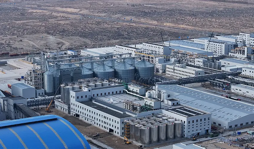

Ethanol plant piping design decides whether a well-planned alcohol process becomes a reliable, maintainable line or a source of leaks, lost product, and startup delays. In an integrated ethanol facility, the pipe is not a passive connection between tanks, columns, and exchangers; it is the control boundary that carries process fluids, absorbs thermal movement, and protects operators. I approach routing from the same integrated-chain view I use for grain storage, fermentation, distillation, and byproduct handling. When a line is hard to drain, impossible to access, or specified in the wrong material, the farm-to-table cost picture gets worse. The guidelines below cover process classification, material compatibility, layout rules, and preconstruction checks.
Ethanol Plant Piping Design Starts With Process Classification
Ethanol plants contain several distinct piping services, and each one imposes different pressure, temperature, cleanliness, and contamination limits. I separate the field into five process groups before writing a single line number: raw corn slurry and mash, fermented beer and stillage, high-proof ethanol and anhydrous product, low-pressure steam and condensate, and utility services such as CIP water, nitrogen, and biogas. That division does more than organize drawings. It sets the material class, gasket selection, valve type, and maintenance strategy for every pipe segment. The mistake I see most often is treating the distillation column as the centerpiece and piping as leftover scope. In a well-integrated alcohol line, we fix the pipe class before the equipment layout is frozen because the line list determines drain points, expansion loops, and instrumentation locations. ASME B31.3 gives the process piping design basis for most plants we plan, while NFPA 30 drives the fire safety decisions around alcohol storage and transfer.
Ethanol Plant Piping Material Selection Must Match the Fluid Service
Material selection in ethanol piping is less about finding one ideal alloy and more about matching each service to the right class. The most expensive line is not automatically the safest.
| Piping service | Preferred material | Reason |
|---|---|---|
| Corn slurry and mash transfer | Carbon steel with wear allowance | Abrasive solids and low proof |
| Fermentation beer line | 304L stainless steel | Organic acids and cleanability |
| Thin stillage and recycle water | Carbon steel or 304L | Temperature and suspended solids |
| Rectified spirit at high proof | 304L stainless steel | Protects product purity and lowers corrosion |
| Anhydrous ethanol product line | 304L or 316L stainless steel | Ultra-low moisture specification and SCC control |
| Steam and condensate | Carbon steel | Standard utility service with traps |

Why Galvanized Steel and Copper Fittings Create Ethanol Piping Problems
Galvanized steel is unsuitable for alcohol service because ethanol attacks zinc and the corrosion products can contaminate the product. Copper and copper alloys are also kept out of fuel ethanol and high-purity industrial alcohol lines; copper ions can promote oxidation-related degradation and create product quality issues. This is not a conservative preference. It is a material compatibility limit that shows up later as filter plugging, gum formation, or an off-spec shipment. For flange gaskets and valve seats, we specify materials rated for ethanol, usually PTFE or high-quality EPDM, and avoid elastomers that soften after prolonged contact with high-proof alcohol.
Choosing the Right Stainless Steel Grade
Within stainless steel, 304L handles fermentation beer, rectified spirit, and general high-proof service in most plants. We move to 316L when the piping sees chlorides, aggressive cleaning chemicals, or consistently high temperature with moisture present. The low-carbon grades are the default because field welding is part of installation, and low carbon reduces the risk of sensitization at weld zones. Carbon steel remains the right choice for steam, condensate, and non-product utility lines, but it needs a documented corrosion allowance and steam trap discipline to keep wet service from accelerating wall loss.
Ethanol Plant Piping Layout Rules Control Drainage and Access
The layout stage is where piping stops being a schematic symbol and becomes a field problem. I have seen otherwise good projects require rework because a long ethanol line swept across a corridor without a single low-point drain. The line worked in the process simulator but failed in the field when water collected in the sag and the product was pushed off spec. Drainage comes first. Every process line needs a continuous slope toward a drain, sampler, or instrument tee; flat pockets and backslopes are not acceptable unless the line is specifically designed for two-phase flow. Vents belong at high points, drains at low points, and dead legs should be shortened to the smallest practical length. Expansion loops and directional anchors have to be worked into the route before the structure is set, not after the pipe rack is installed. Access is the second non-negotiable point. Valves, flanges, strainers, and instrument taps need enough room for a technician to work without standing on a handrail or reaching across a hot steam line. If the routing model shows a valve cluster that cannot be reached from a fixed platform, it is wrong even if the piping stress analysis passes.
If your preliminary P&ID shows a long ethanol run from the distillation hall to the molecular sieve dehydration unit, confirm the low-point drain, expansion loop, and isolation plan before generating the equipment coordinates. Send the drawing to [email protected] and I will review the routing against the process flow.
Distillation and Dehydration Set the Governing Piping Requirements
Once the process moves into distillation and molecular sieve dehydration, steady-state assumptions stop working. The column reboiler steam line, condensate return, overhead vapor line, and reflux piping all live with changing temperature and pressure. A piping design that works for warm beer at atmospheric pressure may fail when steam tracing, thermal expansion, and pressure cycling are added. Molecular sieve units swing between feed, regeneration, and cooling steps. The pipe sees pressure cycles and temperature swings instead of steady service. If the supports assume steady state, the flanged joints at the sieve vessel start working loose during the first few regeneration cycles. I have seen commissioning crews find small leaks at exactly those joints, not because the material was wrong but because the routing did not leave room for the cycle movement. The correct approach is to treat each connection to the dehydration skid as an expansion point, not an anchor.
Distillation also sets the interface between product quality and pipe design. Vapor lines, reflux lines, and condensate systems should be arranged so that low points drain back to the process or to a controlled collection point. Instrument connections need clean service from the line centerline; a transmitter mounted on a dead branch will read a mixture that does not represent the process. For high-proof product lines, flanged connections are kept to a minimum but remain accessible for inspection. This is the point where we check pipe class, gasket compatibility, and stress relief as one integrated review, not three separate tasks.

Preconstruction Piping Validation Catches the Costly Mistakes
Before procurement, we run a structured check on the lines that carry the most risk.
- Lock the process flow diagram and service classifications. The line list must match the actual service conditions, not the equipment name.
- Walk the high-risk routings in the 3D model or across the pipe rack drawings. Look for valve clusters, instrument access, drain points, and ladder conflicts.
- Confirm expansion loops, directional anchors, and stress relief where the pipe connects to columns, dehydration skids, and storage.
- Compare the material classes with the selected gaskets, valve seats, and field welding procedures. The pipe material alone does not fix compatibility; the trim and seal materials do.
- Review low-point drains, high-point vents, and dead legs before the line list is frozen.
If your project includes high-proof ethanol, molecular sieve dehydration, DDGS drying, or fuel ethanol blending, send the process flow diagram and capacity target to [email protected] or call 010-8591 2286. We will review the piping class decisions, line list, and utility interfaces before procurement so the first construction issue does not become a startup shutdown.
Design Teams Ask These Questions About Ethanol Plant Piping Design
How do we choose between carbon steel and stainless steel for ethanol piping?
Carbon steel fits steam, condensate, low-pressure air, and many low-proof services when a corrosion allowance is included. Stainless steel is the standard choice for fermentation beer, rectified spirit, and anhydrous ethanol lines because product purity and corrosion control outweigh the higher material cost. The decision is neither one material for everything nor an automatic upgrade to stainless. We assign each service a pipe class based on proof, temperature, chlorides, cleaning chemicals, and access. That class then drives the valve trim, gasket, and welding procedure. If a project mixes them incorrectly, the carbon steel usually fails first in the weld zone.
Does carbon steel always crack in ethanol service?
Carbon steel does not fail in every ethanol service, and the cracking risk centers on specific stress, water, and oxygen conditions rather than contact alone. High-proof fuel ethanol has been associated with stress corrosion cracking in stressed carbon steel weld zones under certain aerated conditions. Low-proof beer, wet stillage, and utility water lines present far less concern. The practical response is to keep carbon steel in lower-proof utility services and use low-carbon or stabilized stainless grades in high-proof product service. We also keep the pipe stress analysis focused on weld heat-affected zones, not just gross thermal expansion.
What is the most common piping layout mistake in ethanol plants?
In projects we have reviewed, the most common mistake is a line with no continuous low-point drain or with a dead leg that cannot be emptied. A remote ethanol line may look simple on the plot plan, but if it sags between supports or runs into a closed valve, water and alcohol can collect there. That pocket then becomes a source of off-spec product, corrosion, or freezing in colder regions. We prefer drainage-first routing and short dead legs, with instrument and sampler connections located where they can be fully drained. This detail costs little during design and becomes expensive to correct after construction.
When should piping design be fixed relative to equipment layout?
It depends on the project stage and interface complexity, but two positions are safe. If the equipment coordinates are already locked, the piping team routes within that boundary and the line list becomes the control document. If the layout is still open, we fix the pipe class and major expansion loops early, then finalize routing after the equipment model is shared. The worst case is freezing neither and letting piping follow equipment after the fact, which produces field conflicts, extra welds, and drains that slope the wrong way. If your timeline is compressed, share the preliminary P&ID with [email protected] and we will confirm the high-risk piping interfaces before procurement.
If you’re interested, check out these related articles:
Driving Global Food Conservation Through Technological Innovation